An Easy To Build Reflectance Transformation Imaging ( RTI) System just published.
In this article I will describe how to construct a simple reflectance transformation imaging (RTI) setup using an Adurino microprocessor and a 3D printer.
The RTI technique provides a valuable tool for scientists and conservators for the research and preservation of important historical fine art collections. RTI enhanced images prove invaluable for both conservation and fine art authentication purposes. RTI systems are also used in the area of forensic science to photographically record and analyze bullet or projectile striations. Additionally, RTI may be an extremely useful tool for imaging and analyzing pottery fragments, small archaeological tools, and stone artifacts. RTI applications are limitless, and they may provide key visual information for researchers in many investigative areas.
This article was just published in the journal of Bio Communications at ww
w.jbiocommunication.org
See the full journal at www.jbiocommunication.org
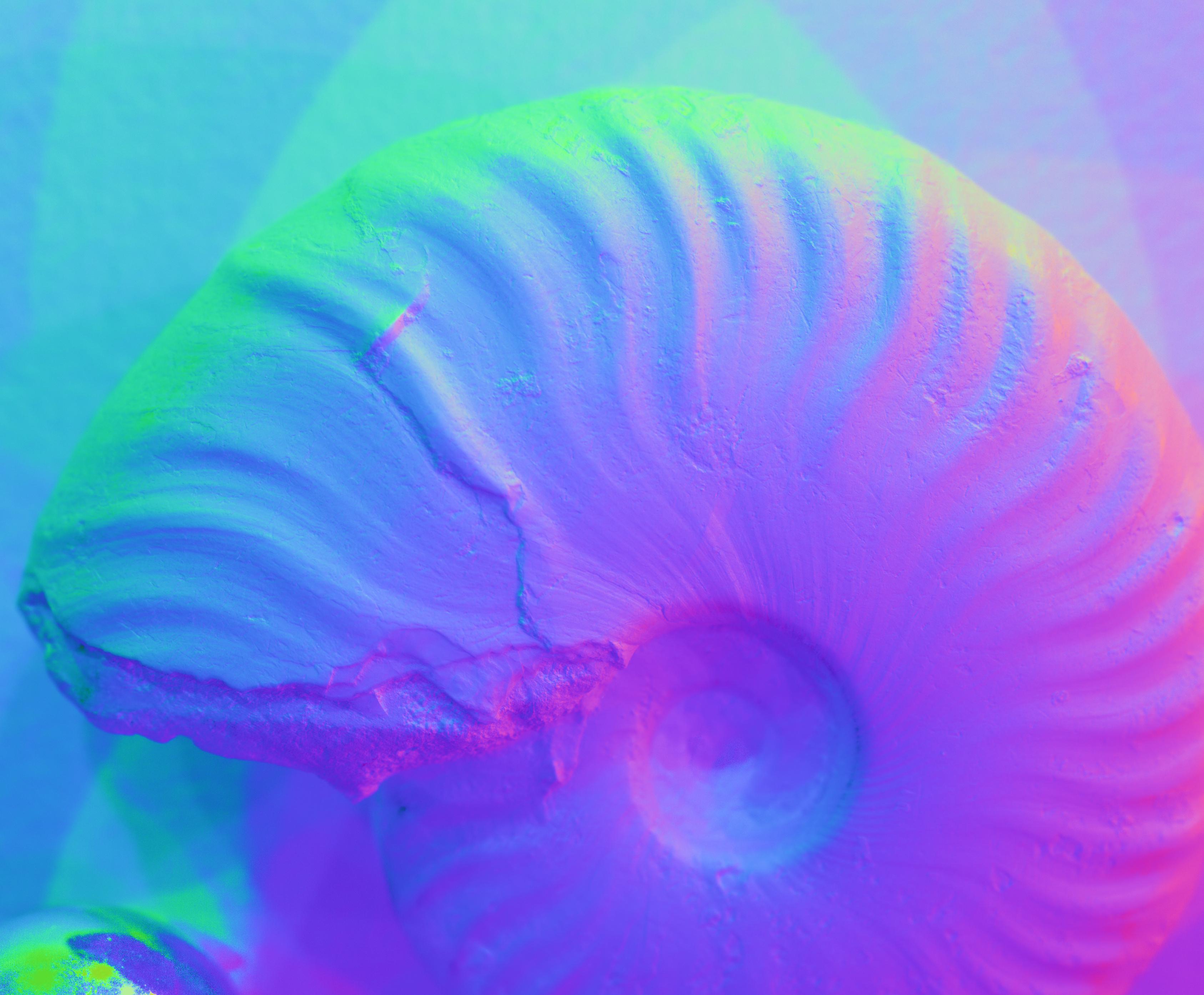
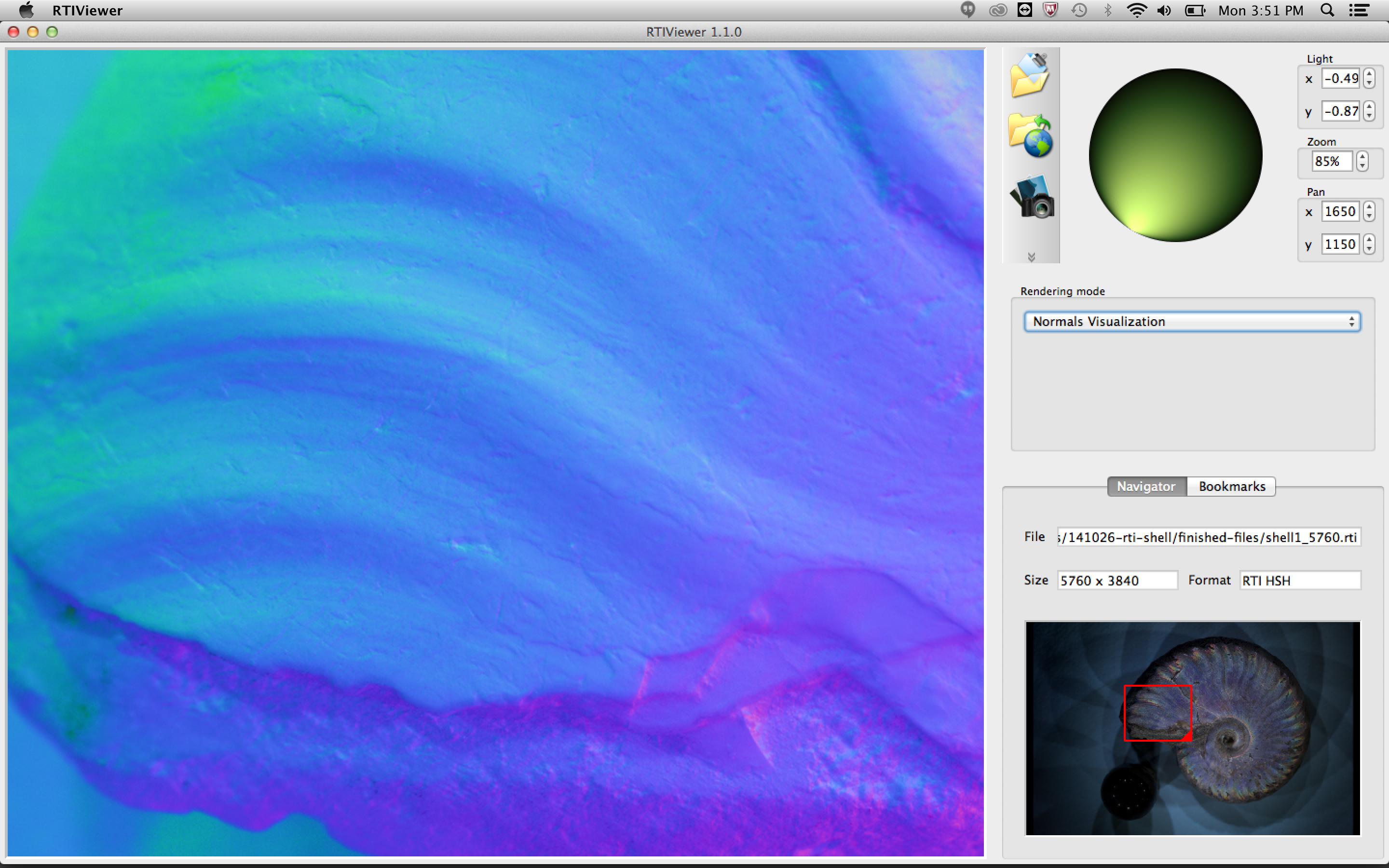
The RTIViewer program shows the close-up of an ammonite fossil. The surface is imaged in the normal vector mode. The different colors represent the direction a particular point of the surface is pointing. This viewing mode can often highlight slight imperfections in the surface of the subject.
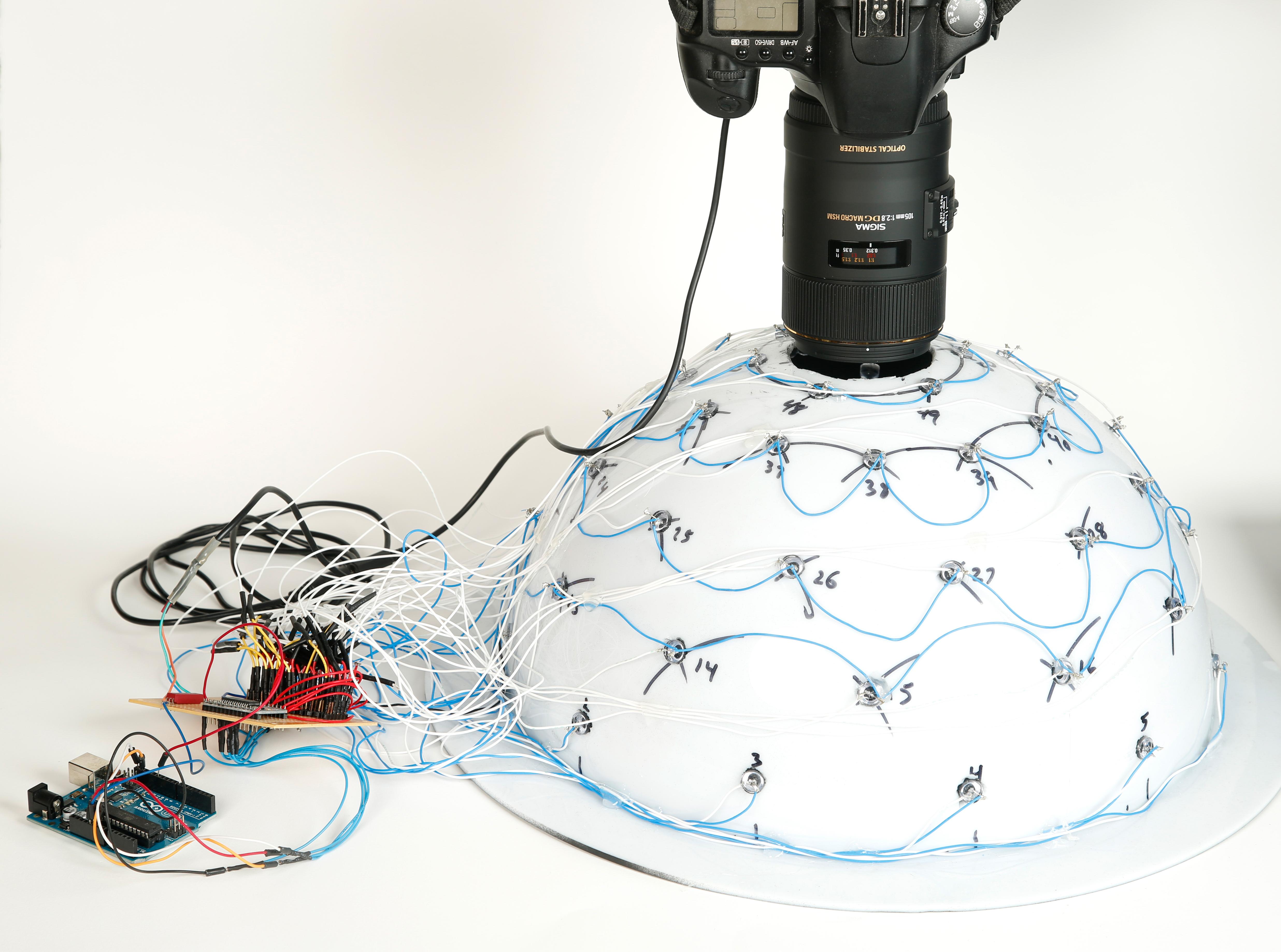
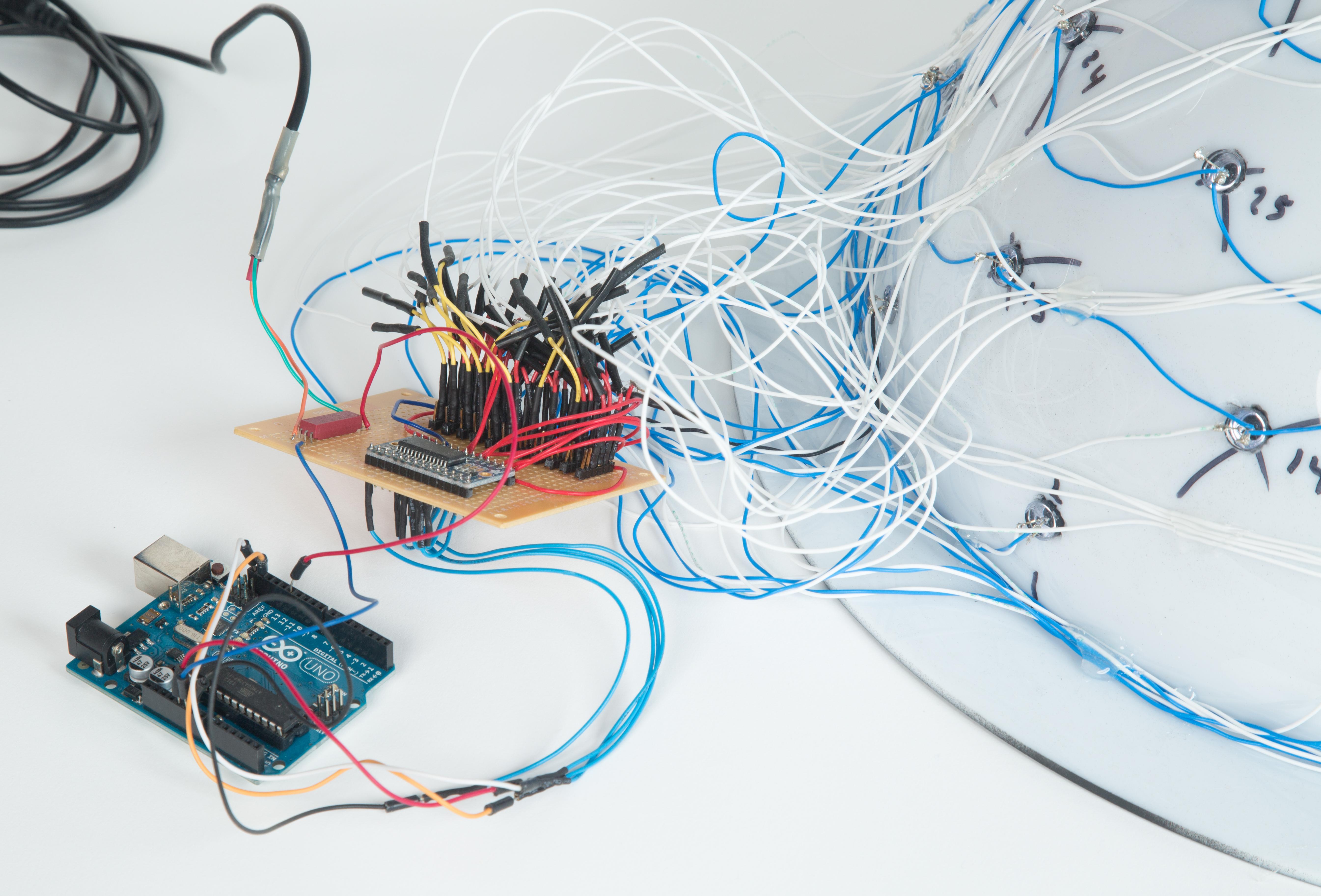
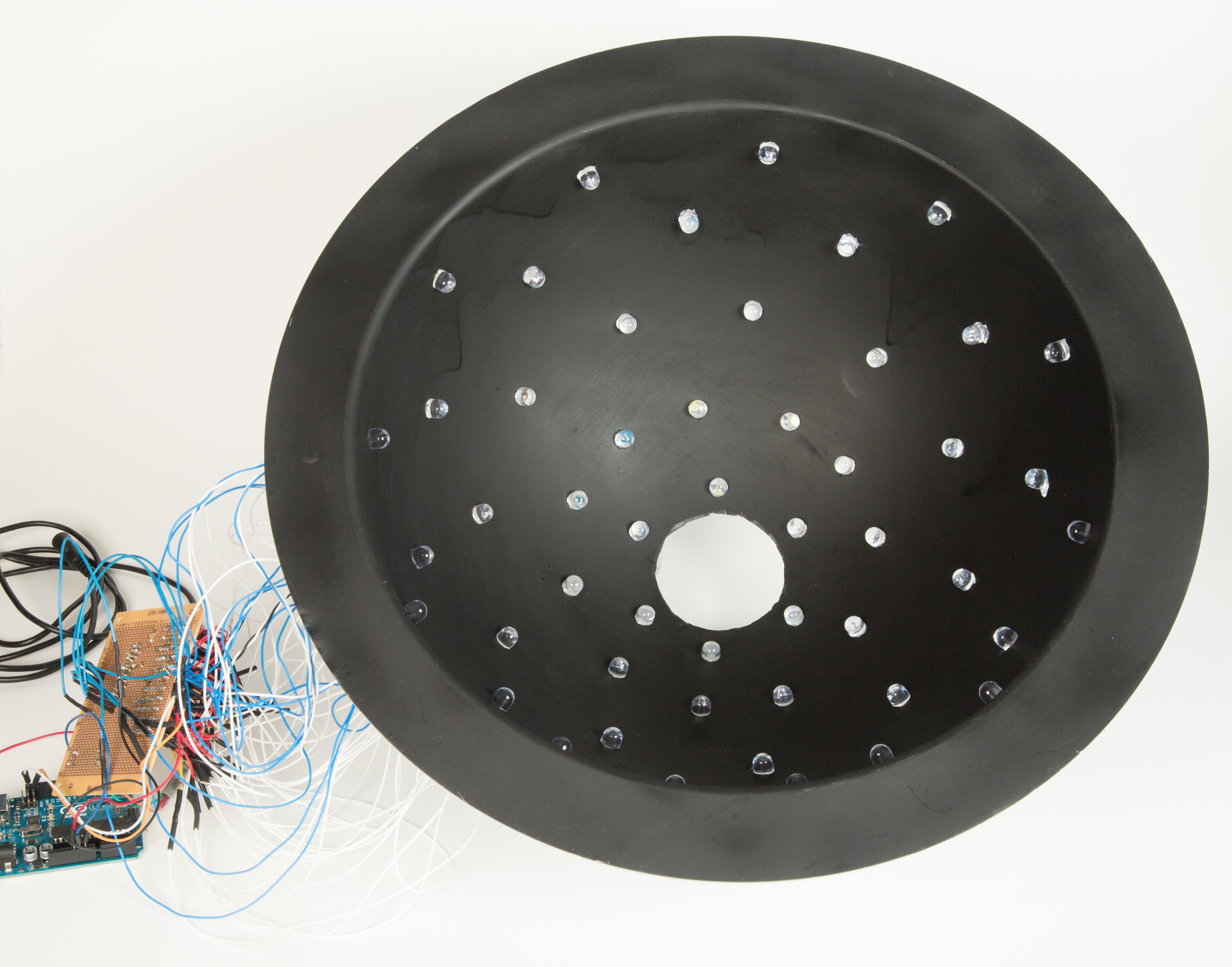
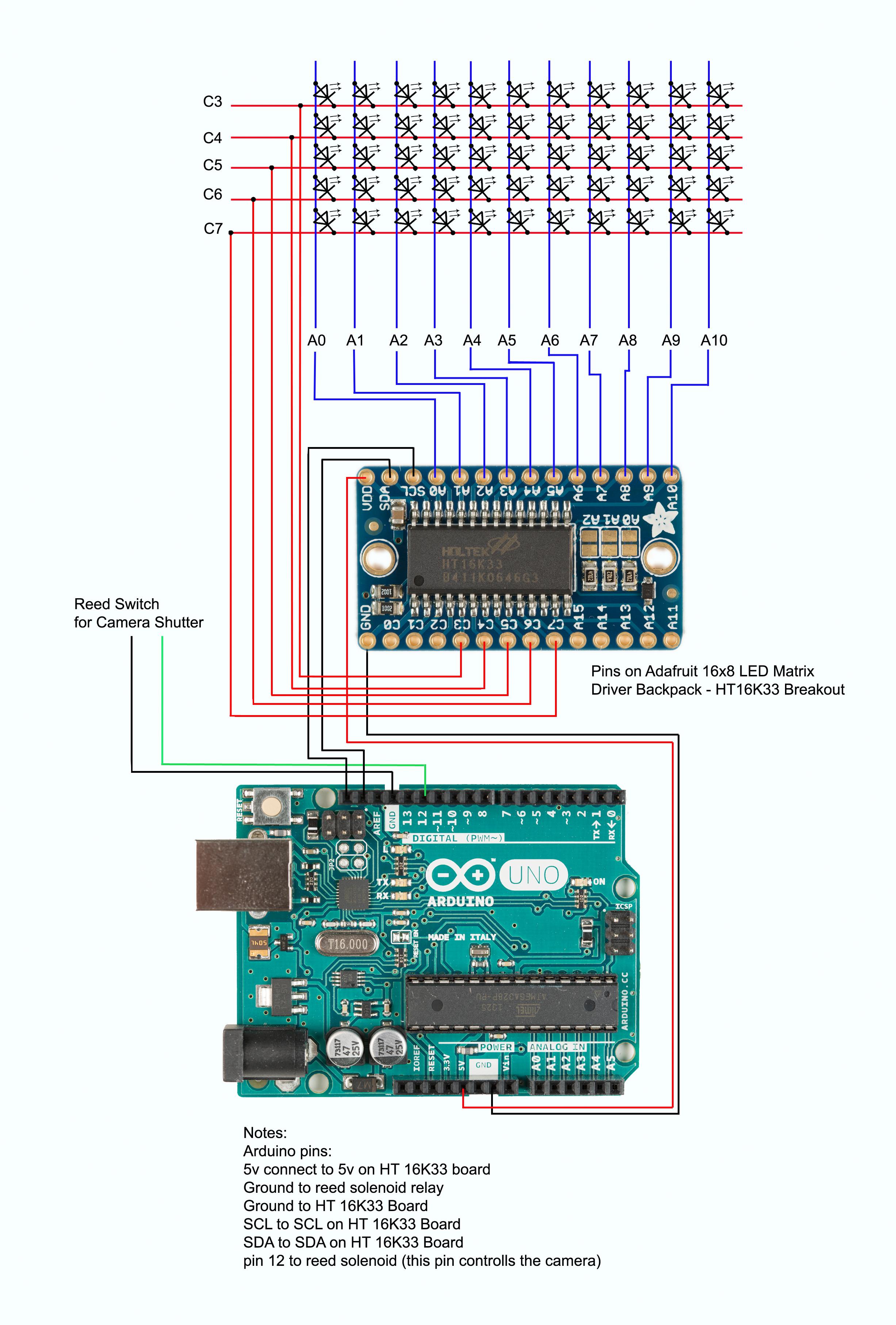
The placement of the camera on the first prototype Reflectance Transformation Imaging (RTI) sphere. The Adruino Uno microprocessor drives an array of LEDs. Each LED is independently controlled to take a set of 50 images that are in turn combined to an RTI file.
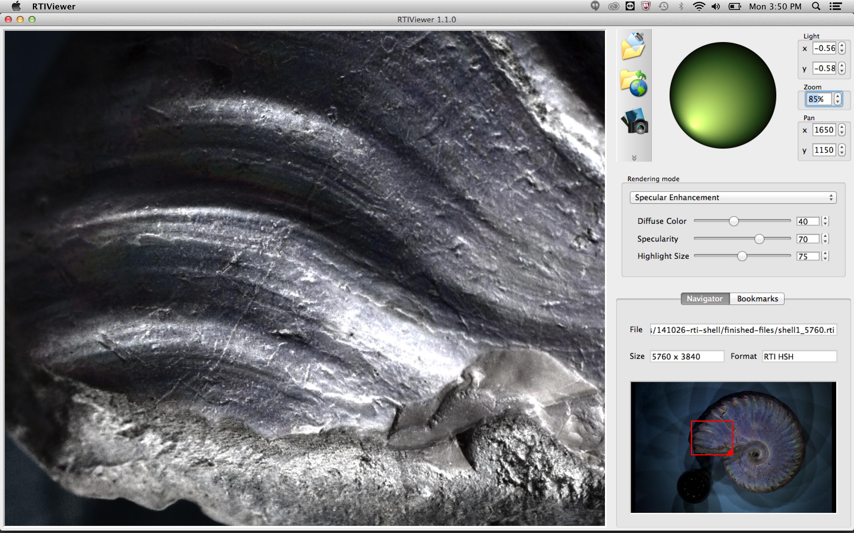
The RTIViewer program shows the close-up of an ammonite fossil. The specular highlights can be adjusted. The lighting angle is controlled by the position of the pointer in the green circle. Desired images can be exported in full resolution.
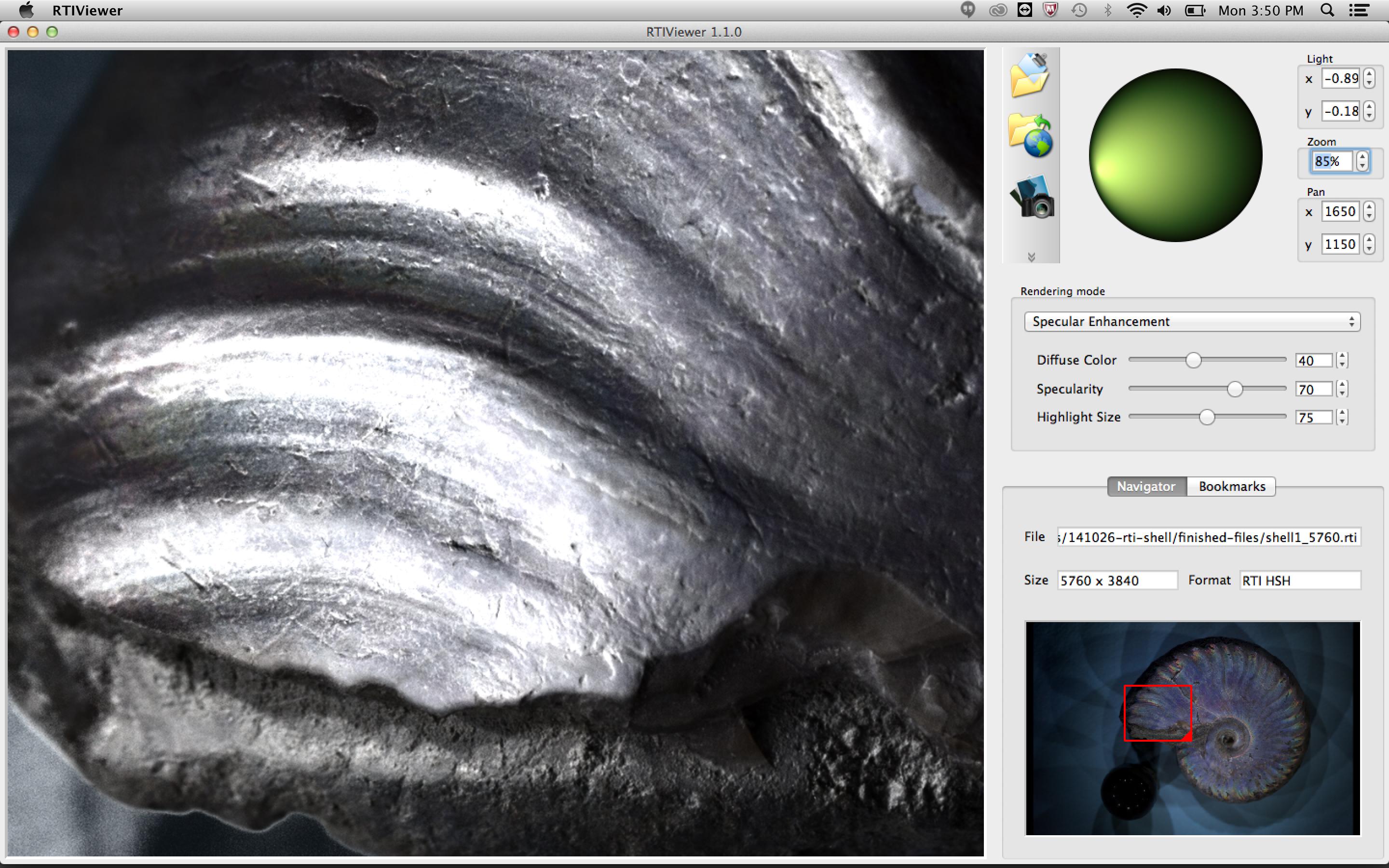
The RTIViewer program shows the close-up of an ammonite fossil. The specular highlights can be adjusted. The lighting angle is controlled by the position of the curser in the green circle. Desired images can be exported in full resolution. The location of the light source is different than figure 1
The RTIViewer program shows the close-up of an ammonite fossil. The surface is imaged in the normal vector mode. The different colors represent the direction a particular point of the surface is pointing. This viewing mode can often highlight slight imperfections in the surface of the subject.
Inside of the large sphere showing the 50 LED lights. Each light is a 10 mm supper bright LED and can be independently controlled by the Adruino Uno microprocessor.
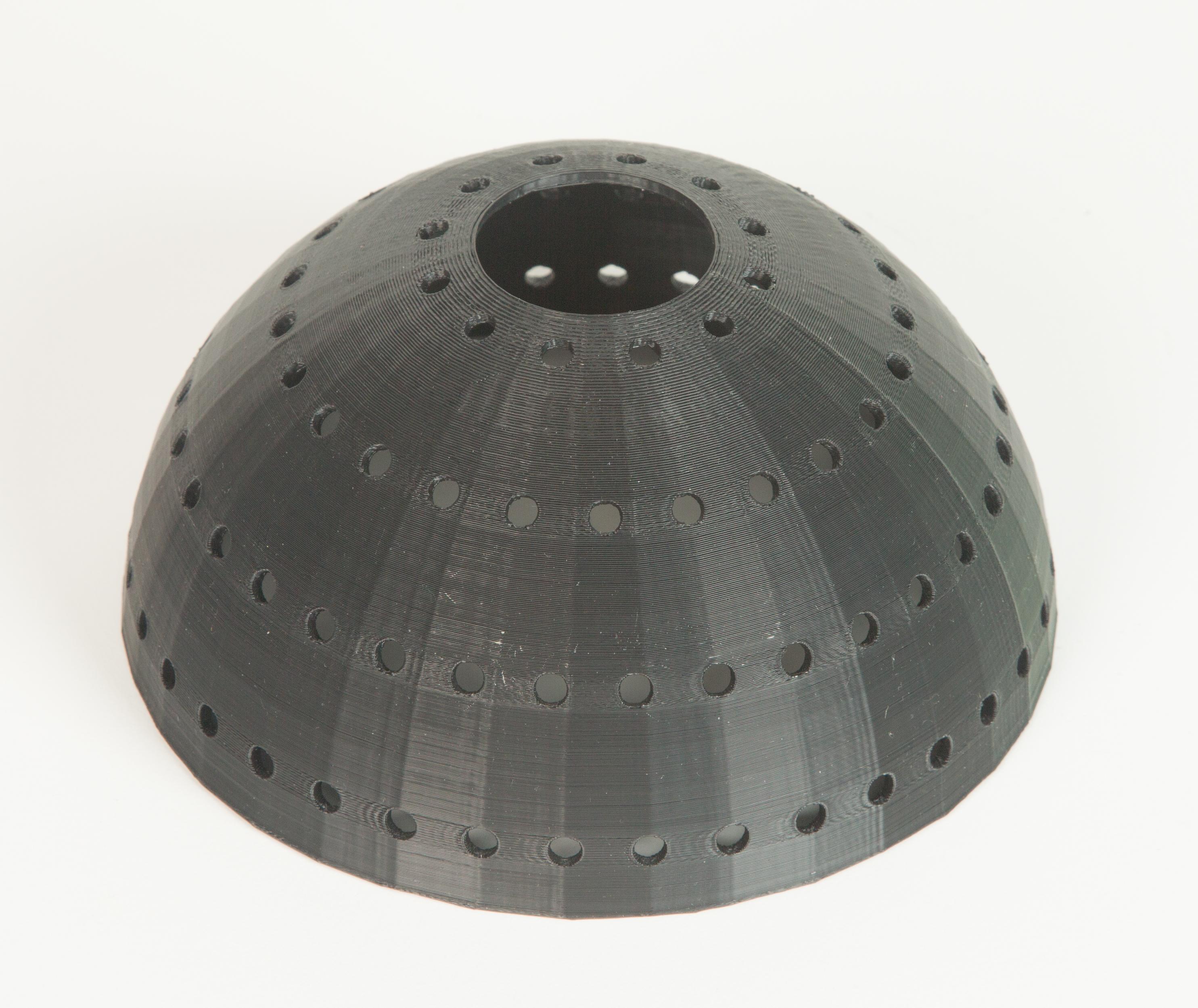
The 3D printed dome for 5mm LED lights. The computer file is available for download and experimentation.


